Attaching Fiber?
We'll make Pole Loading Analysis
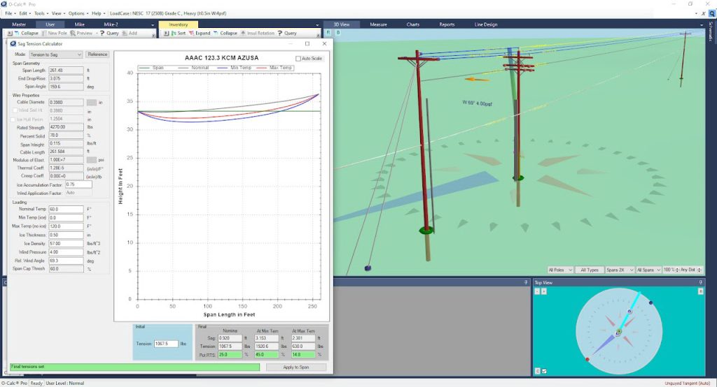
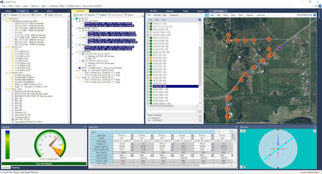
Pole loading analysis is done in Osmose O-Calc Pro v7.00. Among similar software, O-Calc Pro is considered the most powerful and fast, producing comprehensive analysis reports.


What is Pole Loading Analysis
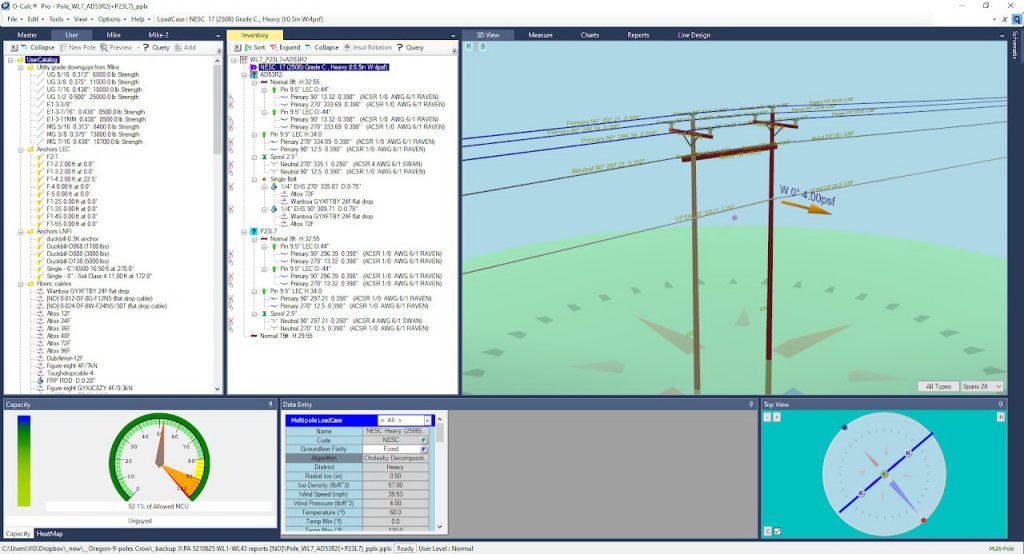
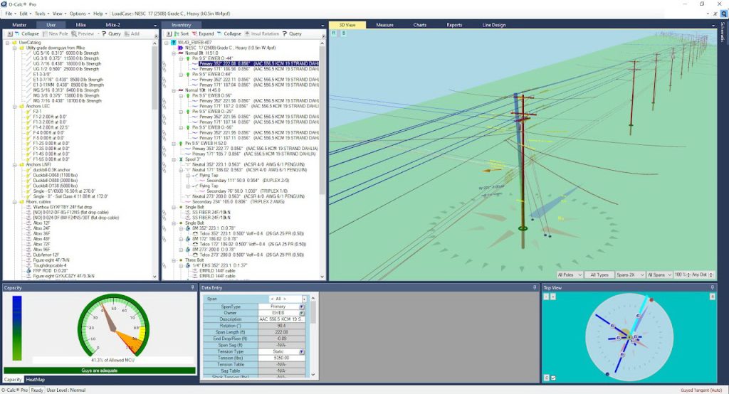
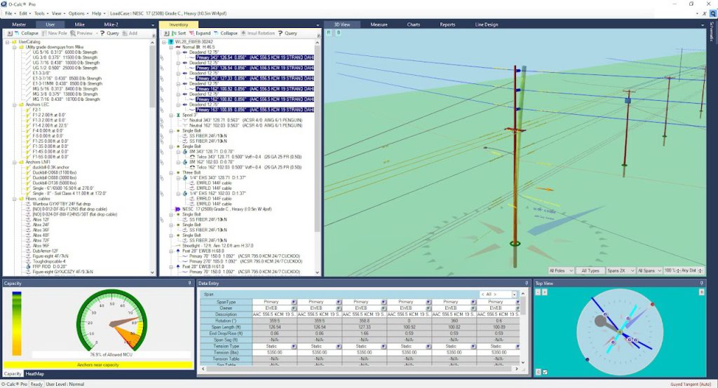
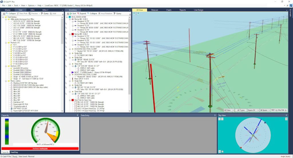
The pole visuals
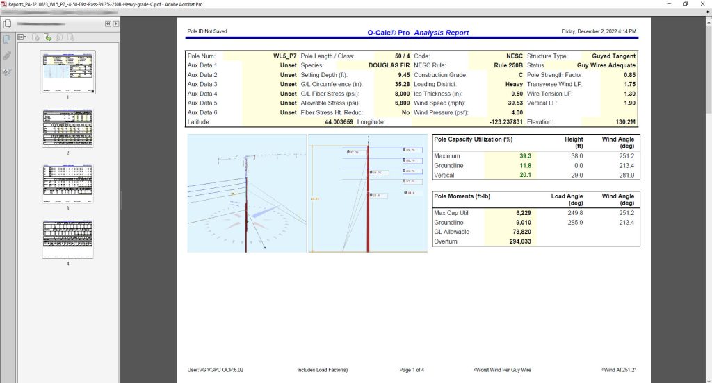
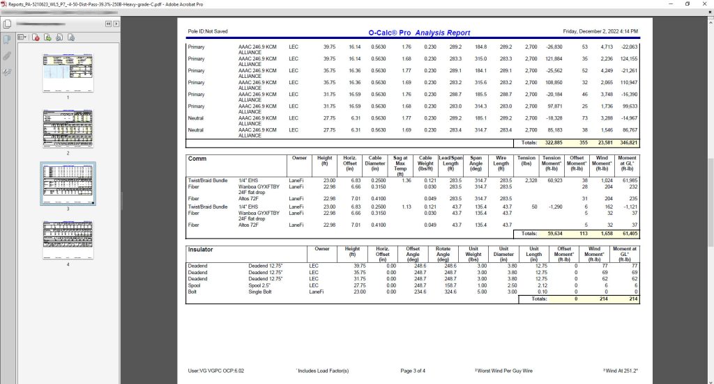
The pole reports
REPORTS
The final result of pole loading analysis is the report file for each and every pole, which shows lateral and vertical pole loading in % compared to maximum allowable loading. Pole loading is assumed as PASSED if the loading is within 85% of allowable (in most cases) according to Table 261-1 of NESC 2017.
Reports are handy in reviewing correctness of such things as anchor placement, downguys tension, braces load, conductor and communication cables tension, etc. Reports show load share between attachers.
PDF / report example 1
PDF / report example 2
PDF / report example 3
What to start from?
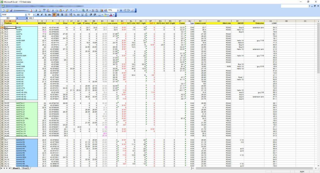
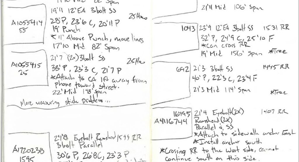
An initial survey is necessary to gather all possible field data concerning poles one needs to attach to. It can be made and presented in different ways, but at least it should bear the names of poles, their height and class. The height of attachment of existing conductors and cables should be collected, as well as existing anchor types and their lead lengths. The type of existing conductors should be requested from your utility company. Field photos should be provided. The appearance of the collected field data does not really matter:
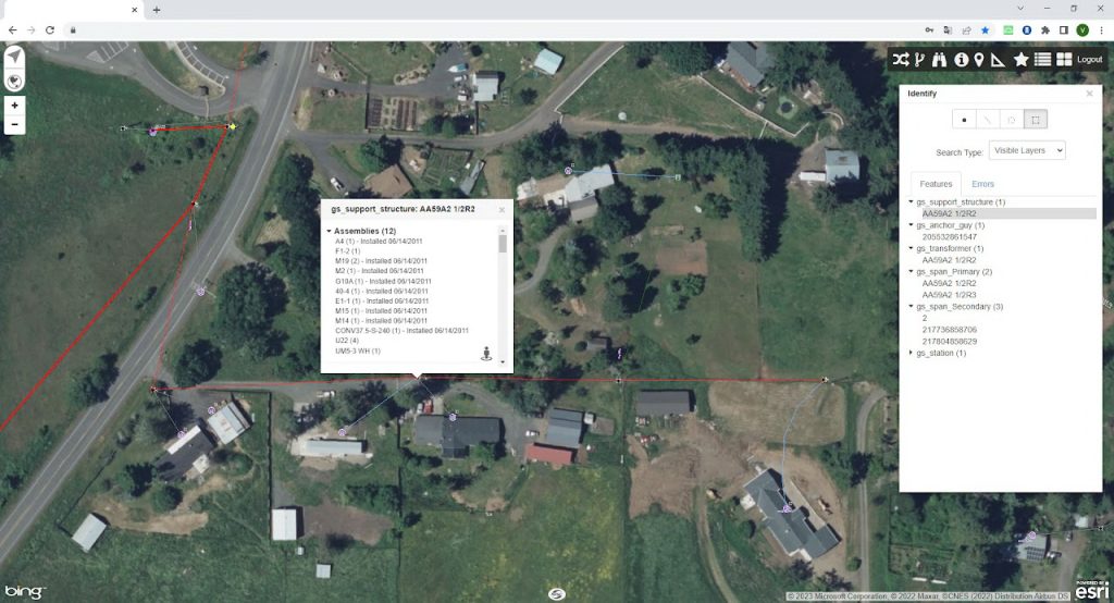
Can be an utility company GIS map, which contains pole data, information concerning framing, equipment, conductor types, etc.
Pole field survey file example: XLS
What you get
- Line design file containing all poles in line (PPLLD)
- Separate pole design files for every pole (PPLX)
- Analysis reports (PDF)
- Pole map / Plan view drawing
- Spreadsheet with pole data, including name, type, coords, make ready requirements, pole loading %, etc.
FAQ
How much does it cost?
Pole loading analysis starts from ~$40/pole and depends on provided data completeness, complexity of work, amount, etc.
How long does it take?
Usually ~1 week per 100 poles.
Where can I attach?
Communication cables are usually allowed to be attached in communication zone 18′ – 23′.
Communication cables must have 40′ separation from supply conductors per Rule 235 Table 235-5 NESC 2017.
What ground clearances should be maintained?
Check NESC 2017 cheat sheet for clearances.
How to determine framing?
Check US DoA RUS BULLETIN 1728F-804 for specifications for 12.47/7.2 kV line construction.
What is the max span of my fiber cable?
A very rough estimation (in meters) can be made as Lmax = (T+1)*10, where T is the tensile strengh of your cable (in kN).
To get the accurate numbers follow the standard rules of cable state calculation.
Why choose PoleFiber
Client testimonials
Highly recommend for any utility looking to streamline pole modeling."


Not convinced?
We are so self-confident that sometimes we even help PUCs resolve design issues with their own attachers.

