Utility pole loading analysis using AutoCAD
As the demand for reliable power and high-speed communication infrastructure grows, utility pole loading analysis has become a vital part of engineering design and safety compliance. While specialized software like O-Calc Pro is commonly used for structural pole analysis, AutoCAD continues to play a valuable role in the overall process, especially for design drafting, layout planning, and integrating pole data into broader engineering workflows.
In this article, we’ll explore how AutoCAD is used in utility pole loading analysis, and how it complements industry-specific pole engineering software.
How AutoCAD supports pole loading analysis
Although AutoCAD does not perform structural calculations natively, it supports the utility pole engineering process in several critical ways:
Site layout and pole placement
AutoCAD allows engineers to create detailed site plans, showing exact pole locations, right-of-way limits, roadways, and existing infrastructure. These layouts are vital for planning pole joint use and fiber ISP pole attachment projects.
Drafting cross-sectional views
Detailed cross-sectional views of poles and attachments can be created in AutoCAD. This visual representation is often required in regulatory submissions or permit applications.
Data integration with structural software
AutoCAD drawings can be exported or referenced in SPIDAcalc or PLS-POLE. These programs may use exported DWG or DXF files as a basis for geometry or layout, helping to link physical positioning with structural modeling.
Custom load annotation and layer management
With AutoCAD’s powerful annotation tools and layer control, engineers can document:
These annotations help provide a complete visual and spatial understanding of pole loading conditions.
As-built documentation
After construction, AutoCAD is often used to create accurate as-built diagrams that reflect actual pole conditions and attachments, useful for wood utility pole analysis, where pole aging and modifications may affect long-term load capacity.
Combining AutoCAD with pole loading software
Here’s how a typical workflow might look when AutoCAD is combined with specialized analysis tools:
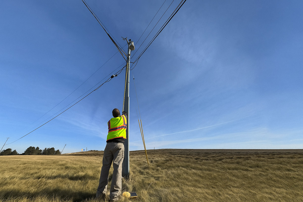
- Field survey. Collect pole data using GPS or LiDAR.
- AutoCAD drafting. Create site layouts, pole details, and equipment positions.
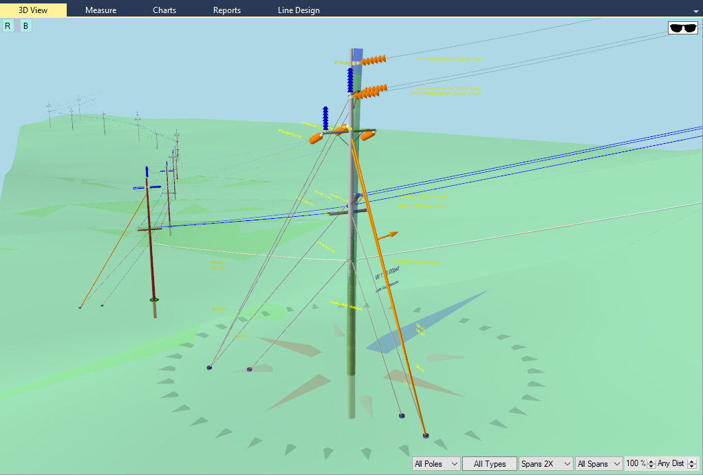
- Export to SPIDAcalc or PLS-POLE. Use layout data to model poles and run load calculations.
- Report generation. Produce pole loading reports, NESC compliance checks, and risk assessments.
- AutoCAD finalization. Update drawings with calculated results, construction notes, and safety zones.
Use case: fiber ISP pole attachment planning
In broadband rollouts, fiber ISP pole attachment plans must often be submitted for permitting. AutoCAD is commonly used to draft these plans, marking:
- Proposed attachment height
- Existing attachments (electric, telephone, cable TV)
- Clearance measurements
- Route maps
This is particularly important in pole joint use scenarios, where multiple providers share limited space on a pole.
Final thoughts
While AutoCAD does not replace specialized structural analysis tools, it remains an indispensable part of the utility pole loading analysis workflow. Its strengths in precision drafting make it ideal for site planning and mapping, construction detailing, regulatory compliance, etc.
By combining AutoCAD with tools like O-Calc, utility engineers can create efficient, safe, and code-compliant designs that support modern infrastructure needs.